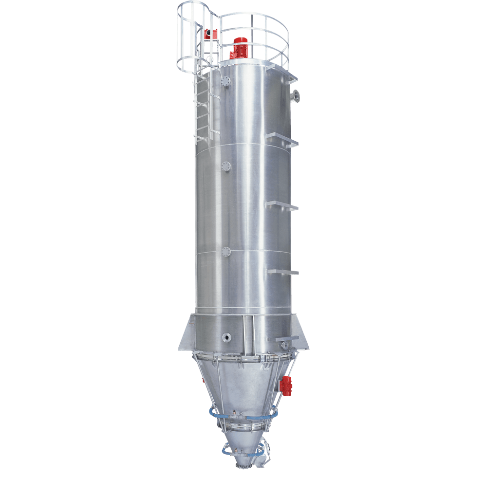
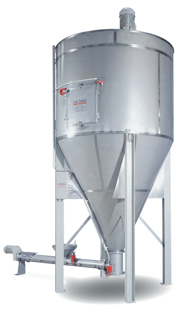
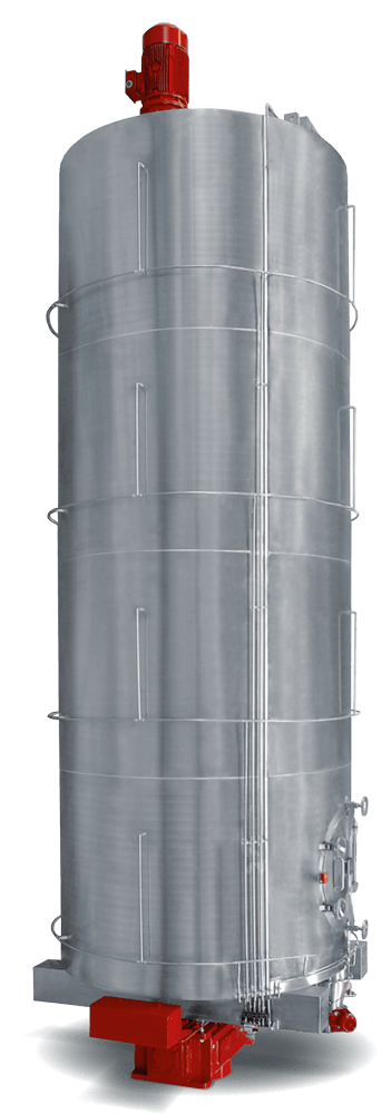
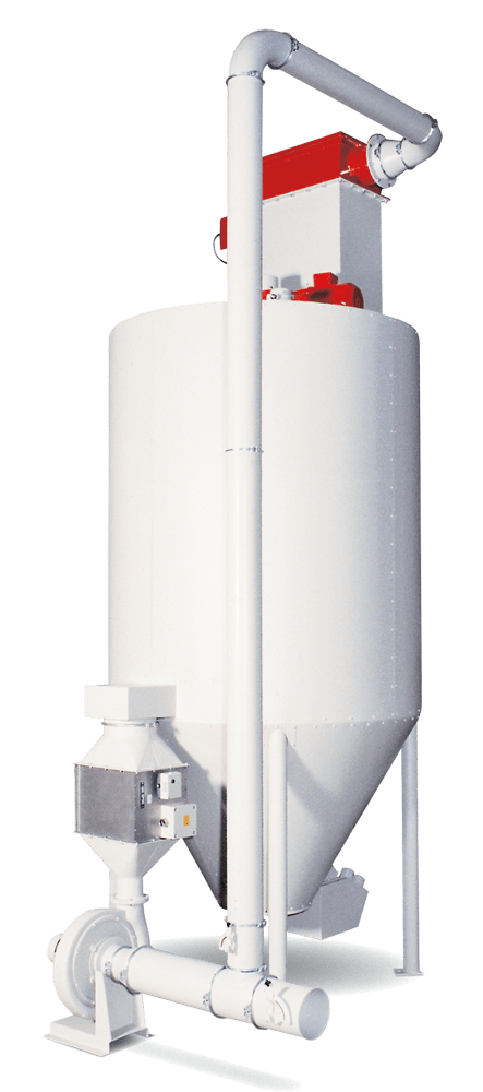
RMS series
Horizontal and vertical flows in the RUBERG mixing silos mix the entire silo contents in large volumes and in a short time. Equipped with an insulated double jacket, thermal mixing tasks can be carried out in the RUBERG mixing silo. As a mixing silo with a useful volume of 100 – 20.000 litres or as a large-capacity mixing silo with up to 100 cbm capacity. Standing vertically, they are suitable for indoor and outdoor installation. Low operating costs due to low drive power and low-maintenance and low-wear design.
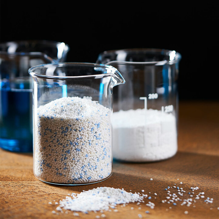
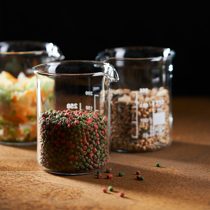
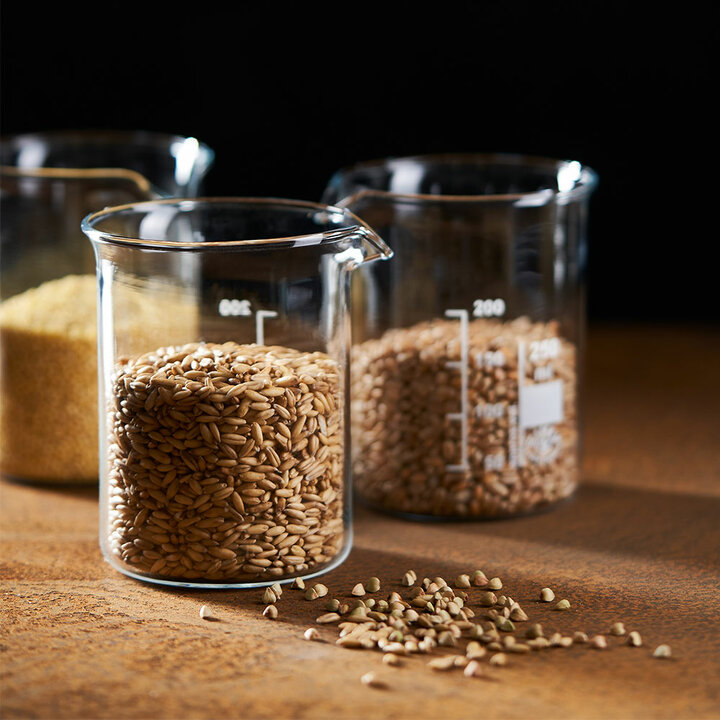
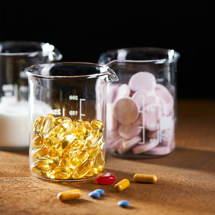
Mixing silos of the RMS plus series are suitable for the production of demanding dry material mixtures in very large batches. They are used in sensitive production areas, such as the pharmaceutical, chemical and food industries through to bulk materials in the building materials and animal feed industries.
Info & downloads
Example tasks:
- Mixing
- Homogenizing
- Inerting
Application areas:
- Building materials
- Animal feed
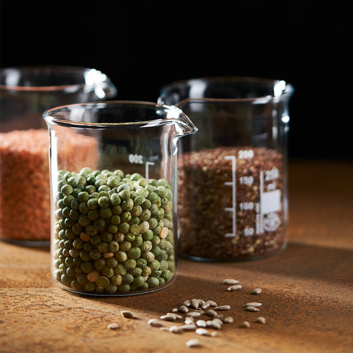
- Cereals
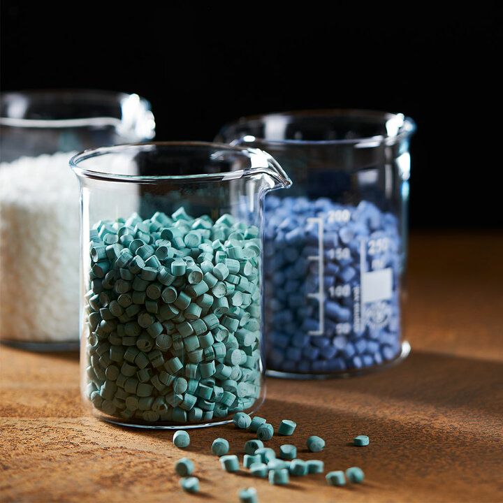
- Plastics
Other mixer types
Industries & products
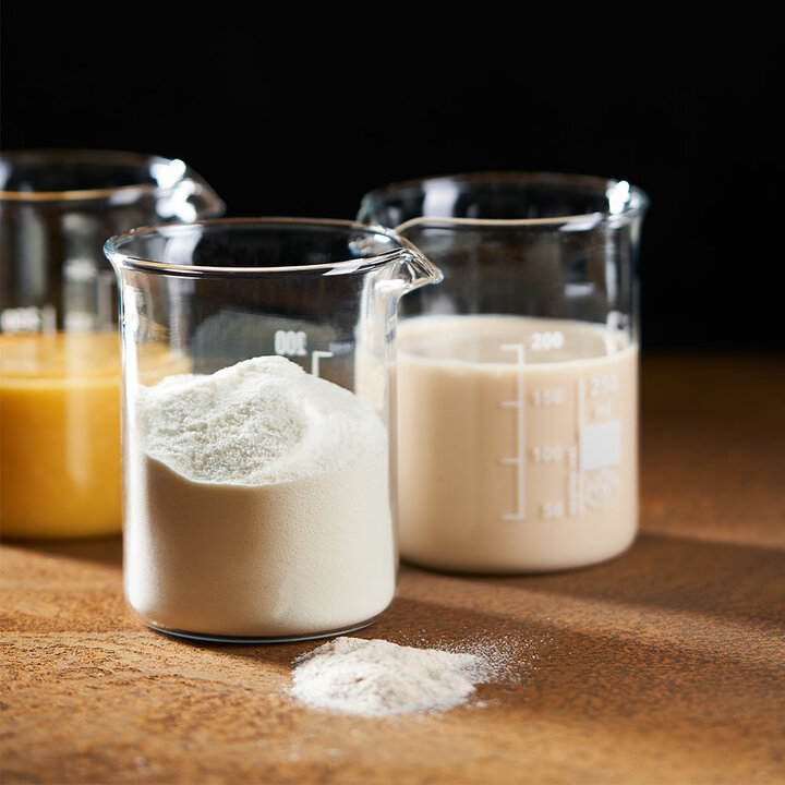
Baby food
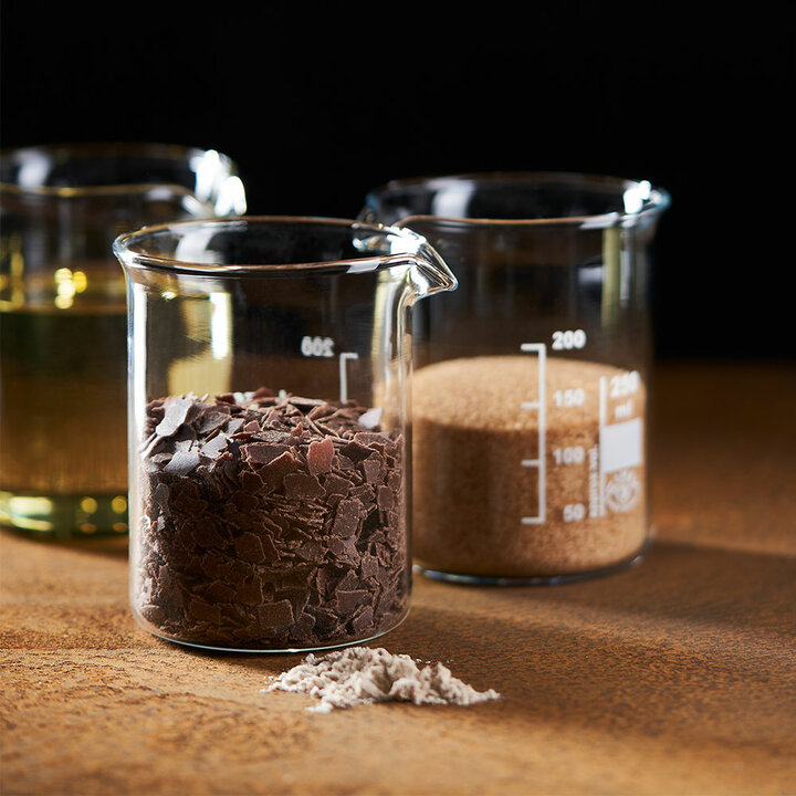
Baking agents
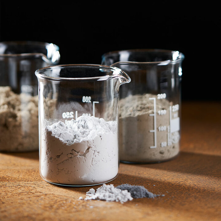
Chemistry
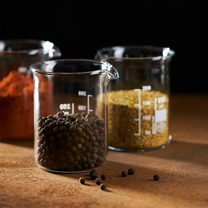
Spices
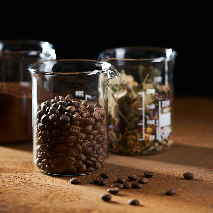
Coffee & tea
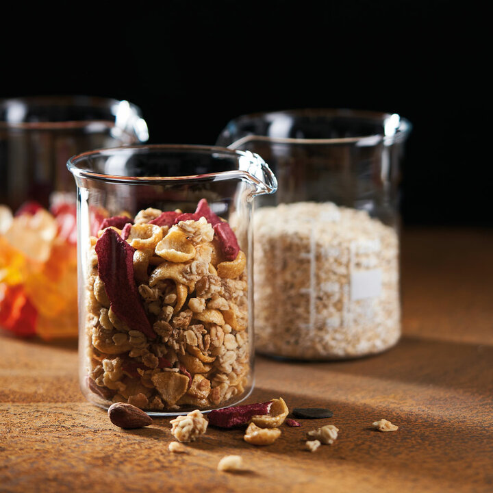
Food
Oilseeds
Pharmacy
Ask us!

Would you like a consultation, more information on this machine solution or are you generally looking for a customised overall solution? – Get in touch with us now... Of course, you can also call us directly: Phone number: +49 (0) 5274-98510-0.
We look forward to your inquiry.